|
Home
»
Mechatronics
»
Mechatronics
Products
»
VIRTUAL DRIVING SYSTEM (VDS) |
| |
|
VIRTUAL
DRIVING SYSTEM (VDS)
Driveline Modeling (A
Forward-Facing Approach) |
| |
A driveline system is a
complete mechanical system, which includes: engine, clutch, transmission,
differential (final drive) and its shafts, brake, wheel, chassis, air drag,
and driver. In the auto industry there is always a great need to analyze such a
system and to be able to monitor performance of each contributing
subsystem. However, at the present time there is no particular CAD / CAE
tool that can model and analyze a complete driveline system. In the absence
of a CAD / CAE model, other approaches have been utilized.
There are two approaches in modeling and simulation of the driveline
systems; backward-facing and forward-facing. There are currently some
products on the market that are based on backward-facing approach. In
a backward-facing approach, the speed is applied to the wheel and the
performance of other subsystems is monitored. It is assumed that the vehicle
met the drive-cycle speed and a model of a driver is not required. This
approach is against the direction of the physical power flow in the vehicle
and is not well suited to computing the best-effort performance.
The VDS product performs the modeling and simulation of the driveline of a
car based on forward-facing approach. In a forward-facing approach, the driver
model uses the drive cycle and the actual speeds to develop appropriate
accelerator and brake commands. This approach is in the direction of the
physical power flow in the vehicle (more physical) and is well-suited for
hardware development and detailed control simulation. Dynamic effects can be
included naturally in a forward-facing approach, but they are not included in
a backward-facing approach. Thus, simulations using the backward-approach tend
to execute faster than the forward-facing approach. The modeling of the
components is done with VHDL-AMS language based on mathematical equations
related to each component. The components modeled are engine, clutch,
transmission, differential (final drive), shaft, brake, wheel, chassis, air
drag, and driver. The components have been connected based on a forward-facing
approach and simulated during a European Driving Cycle. The vehicle is assumed
to be driving in longitudinal motion and on a road without slope.
The driveline parts are connected as shown in Figure 1. The model is
simulated in a European driving cycle and some interesting variables are
plotted. |
|
|
|
|
|
Figure-1
(Schematic for complete driveline model) |
|
|
|
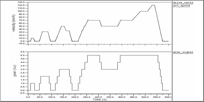
The driveline model has
been simulated in a European driving cycle, lasting for 595 seconds. Figure
2 shows the reference (drive cycle) speed that the car shall follow,
together with the actual (measured) vehicle speed and the gear signal. The
difference between the reference speed and the vehicle speed is mainly due
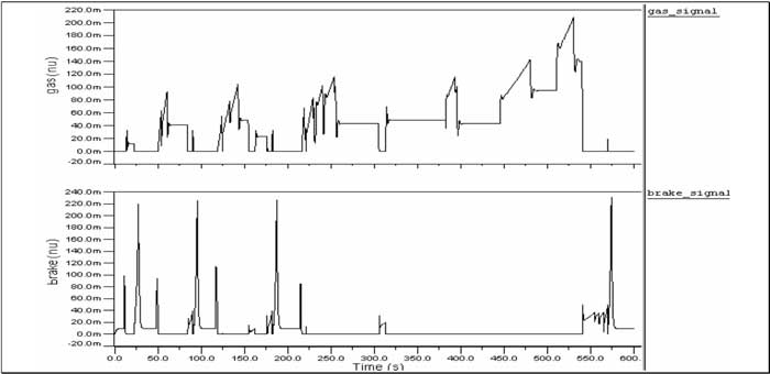
to the driver model. Figure 3 shows the brake gas and break pedal signals. |
|
|
 |
|
Figure-2 (Drive-cycle/actual speed and Gear signals with respect to time) |
|
|
 |
|
Figure-3(Gas and break pedal signals with respect to time) |
|
|
|
If you need any information
about this Product please
click
here and submit your query.
You will be contacted shortly
by one of our experts. |
|
|
|
Copyright © 1993-2005 Mechatronics Inc. All Rights Reserved |
|
|
|