|
Home
»
Mechatronics
»
Mechatronics
Products
»
High Power Electrical
Systems |
|
|
|
High Power Electrical
Systems
|
|
This product is a highly
integrated Mechatronics product consisting of mechanical, electromagnetic, and
electromechanical components and subsystems of a car modeled based on 42V
technology. The product enables users to perform simulation, and analysis of
components and subsystems of a dual voltage system.
Note: Generic products with similar functionalities are available on the
market for up to 100k per copy. This product is, however, much more specific
compared to generic products and when 42v becomes the auto industry standard; it
has the potential of becoming Mechatronics Inc. number one product.
Using MAST, Saber Simulation Environment modeling language, models for all
components used in the dual-voltage system are developed, e.g., the
alternator, batteries, DC/DC converter, and loads. By simulating the system,
the flow of power through the system was monitored as the power supply and
demand changes with vehicle speed changes (drive-cycle) and load on-off
transitions (load-cycle). The simulation results, and in particular, the
final battery state of charge at the end of each transient analysis, were
then used to make judgments regarding the sizing of the power supply
components
The basic dual-voltage system consists of two buses; one supplied by the
existing standard 12V battery and regulated at 14V, and the other supplied
by a 36V battery and regulated at 42V. All high-power loads are located on
the 42V bus. All low-power loads are placed on the 14V bus. Two scenarios
have been analyzed; dual/single alternator systems.
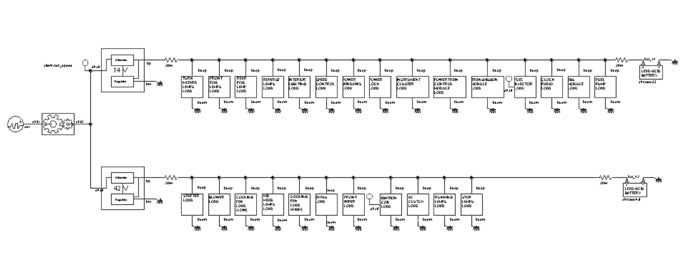
• Dual Alternator System; is based on two alternators providing both high
(42V) and low (14V) voltage outputs.
|
 |
|
Figure 1
Saber design of dual alternator system |
|
|
|
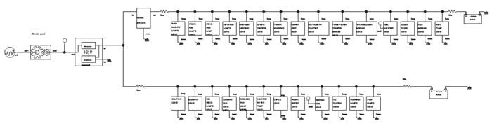
•
Single Alternator System; is
based on one alternator providing high (42V) voltage output. The lower
voltage (14V) is derived from the high voltage bus by use of a dc/dc
converter. |
|
|
 |
|
Figure 2 Saber design of single alternator system with DC/DC converter |
|
|
|
List of loads modeled in
the product are as follows. |
|
42 Volts Loads |
14 Volts Loads |
Small Loads |
|
StarterFuel
Pump
Blower Motor
HID Headlamps
Cooling Fan
Electric Water Pump
EHPAS Motor
Front Motor Wiper
Ignition Coils |
AC Clutch
Interior Lighting
Front Fog Lamps (Bulb)
Rear Fog Lamps (LED)
Running Lamps (LED)
Stop Lamps (LED)
Turn/Hazard Lamps (LED)
Reversing Lamps (Bulb) |
Speed Control
(Electronic Throttle)
Power Windows
Power Locks
Instrument Cluster
Powertrain Control Module
Transmission Module
Fuel Injectors
Clock/Radio
ABS Module |
|
|
|
|
To evaluate the power flow in
the dual-voltage system, the system’s supply and demand of power under
typical driving conditions needed to be simulated. This required the use of
two types of data: drive-cycles or engine speed profile and load-cycles. The
length of the engine speed profile used is 800 seconds. A number
of standard and non-standard drive-cycles exist and are used in the industry.
Table 1 lists each drive-cycle used in this product and a brief
description of each. |
|
|
|
Table 1
Drive-cycles used in simulations |
|
Drive-cycle |
Description |
|
(CLCC -
summer) City Load Carrying Capacity |
Simulates low
speed city driving in summer |
|
(CLCC -
winter) City Load Carrying Capacity |
Simulates low
speed city driving in winter |
|
(IDLE -
summer) Engine Idle Cycle |
Simulates
stopped or slow traffic in summer |
|
(IDLE -
winter) Engine Idle Cycle |
Simulates
stopped or slow traffic in winter |
|
(CNL) Country
Night Load |
Simulates
highway driving |
|
|
|
|
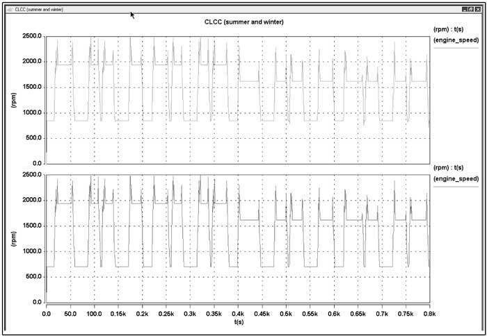
Figure 3 below shows two
typical drive-cycles (CLCC summer and winter, respectively), the engine
speed in revolutions per minute plotted against time in seconds. Engine idle
speed is 850 rpm for summer and 700 rpm for winter. Engine speed for Country
Night Load (CNL) is 2752 rpm. |
|
|
 |
|
Figure 3
City Load Carrying Capacity engine speed profiles used in dual alternator
system (in summer and winter) |
|
|
|
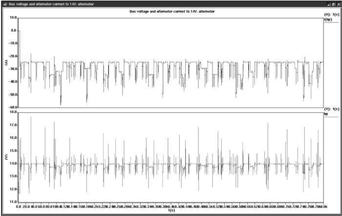
Besides specifying the car’s
speed, which determines the amount of power that can be supplied to the
system by the alternator, it is also necessary to specify the sequence of
load events, which will demand power from the electrical system.
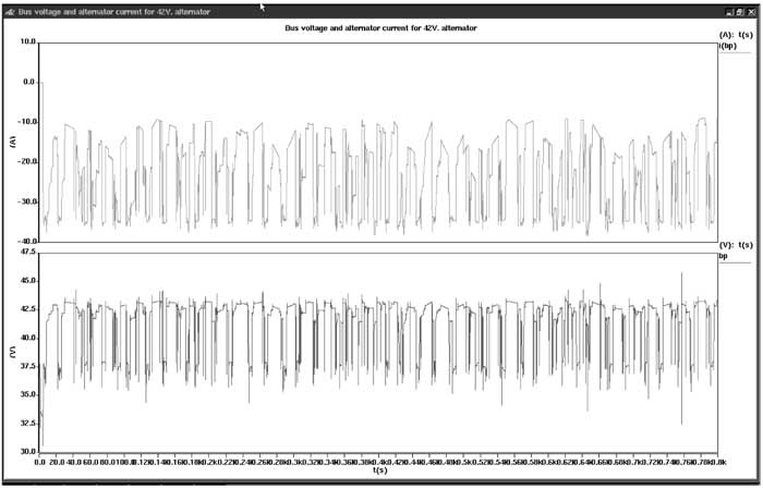
Figure 4 (14 volts) and Figure 5 (42 volts) show alternator currents and bus
voltages for CNL drive-cycle for the dual alternator system. |
|
|
 |
|
Figure 4
(14 volts) bus voltage and alternator current for 14 volts alternator (CNL) |
|
|
 |
|
Figure 5
(42 volts) bus voltage and alternator current for 42 volts alternator (CNL) |
|
|
|
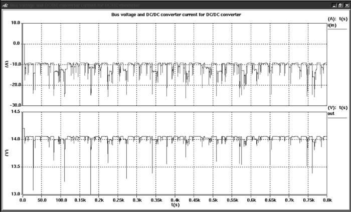
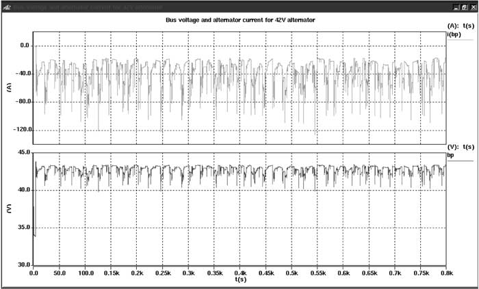
Figure 6 (14 volts) and
Figure 7 (42 volts) show DC/DC converter and alternator currents and bus
voltages for CNL drive-cycle for the single alternator system.
|
|
|
 |
|
Figure 6 (14 volts) bus voltage and current for DC/DC converter (14 volts
side) (CNL) |
|
|
 |
|
Figure 7 (42 volts) bus voltage and alternator current for 42 volts
alternator (CNL) |
|
|
|
If you need any information
about this Product please click
here and submit your query.
You will be contacted shortly
by one of our experts. |
|
Copyright © 1993-2005 Mechatronics Inc. All Rights Reserved |